
Introduction
When I embarked on this project, I knew I would be living with the results for a long time. I wanted to make sure I got as much of this project "right" as possible, and so I consulted many message boards for information from the real experts of Do-It-Yourself speaker building. I also wanted to make sure the speakers were finished nicely. I knew raw MDF wouldn't sit well with my parents, nor would it sit well with my future wife. I first received my inspiration for this project in November of 2002, as I viewed the contents of the Definitive Technology buyout at Parts Express. It occurred to me that it was the best chance I would have to build a pair of nice listening speakers before I went away to college. Until then, I was using a pair of speakers with Pioneer 1.5" Phenolic Ring cone tweeters and 8" clear polypropylene woofers in a pair of cabinets that were originally used for the Fried Model Q from the 1970s. I enjoyed the sound I got out of these speakers, but I knew I could do much better than the cone tweeters and the large woofer. There was great emphasis placed on the midbass region, which gave Ska horns a pleasant fullness, but the overall sound from the Pioneer/Frieds left a good deal to be desired. The drivers from the Definitive buyout that really caught my eye were the Seas H537 dome tweeter and the 5-1/4" cast-aluminum frame midbasses.
This web page is devoted to my journey through the process of designing and constructing this pair of high-quality loudspeakers. I do not own any testing equipment, so it is not possible for me to post frequency response graphs. I can, however, offer you my own personal analysis of the sound of the speakers. I will tell you right now that I feel I have achieved what I set out to do, which was build a pair of speakers with high-quality cabinets and drivers with high-quality crossover and output fidelity comparable to that of Definitive's own speakers, to build a pair of speakers that I would not constantly feel the bite of the upgrade big while listening to and a pair that I could be content with for a long time to come.
This page has lots of photos. Click on any photo to enlarge it. Be warned: the full-size high-resolution photos are large in size. You might just go grab a cup of coffee while you wait for them to load.
The Drivers
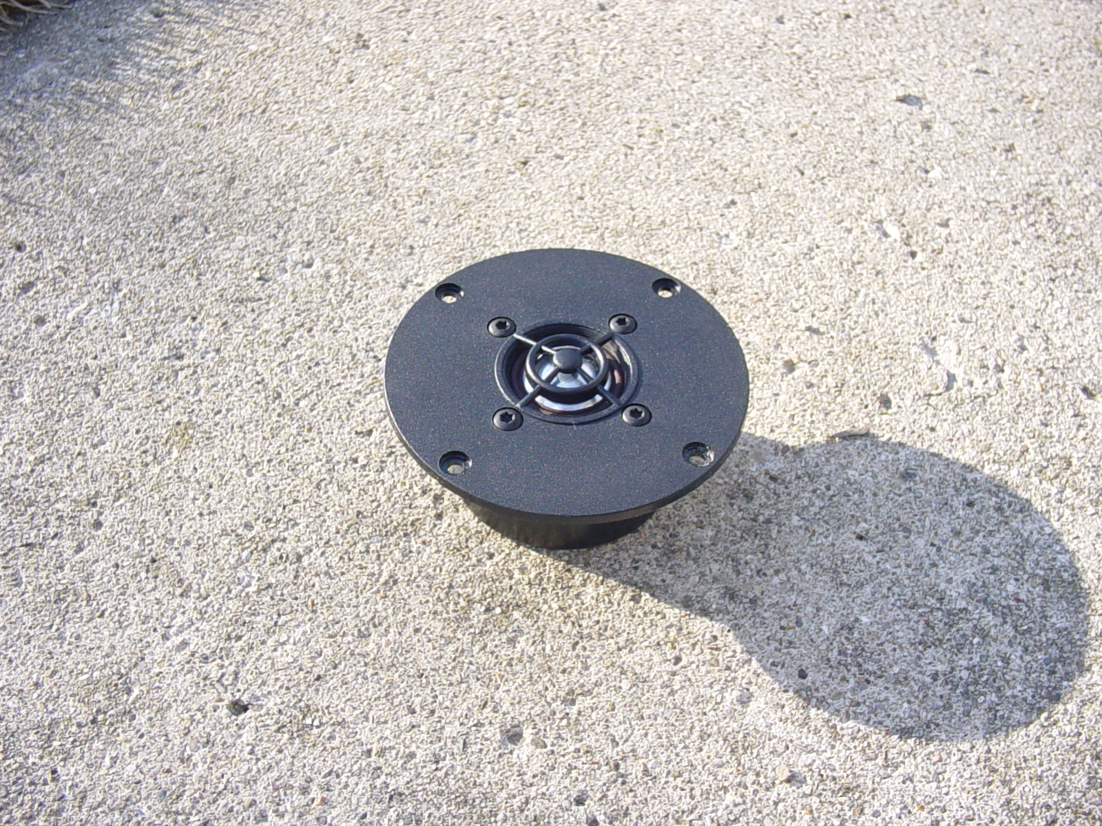
Seas H537-06 Aluminum Dome Tweeter

 (Click to Enlarge)
(Parts Express #279-312) This is a fine-looking tweeter, but what initially caught my eye about it was the Seas brand name. Seas of Norway is regarded as being in the highest echelon of manufacturers of speaker drivers, right about on the same level as Vifa in their standard line. and about even in competition with Scan-Speak in Seas' Excel line. I looked at the features that the driver offered and knew that I would not be disappointed with this tweeter. Its features include a glass-reinforced poly faceplate with a protective and functional diffuser, a large vent in the pole piece to a damped rear chamber, ferrofluid damping, a copper voice coil wound on an aluminum former, and a low Fs. What really sealed the deal for me was the opportunity to read a review of the version of this tweeter that did not feature a damping chamber. The person giving their opinion stated that this was a very smooth, natural-sounding dome tweeter without a lot of the harshness that most aluminum domes have trouble with. For $14 apiece, this tweeter really has impressed me. This tweeter is the same tweeter that is used in Definitive's big bipolar towers that have received great reviews.
Driver Specifications
Manufacturer: SEAS of Norway
Model/Manufacturer Part Number: H537-06
Diaphragm Type: Dome
Diaphragm Material: Aluminum
Diaphragm Diameter: 1”
Faceplate Diameter: 4”
Cutout Diameter: 3¼” with notch for terminal*
Dome Surround: Fabric
Voice Coil: Copper on Aluminum Former
Ferrofluid Cooling: Yes
Other: Rear damping chamber, protective diffuser
Power Handling: 90 watts RMS, 150 watts max.
Nominal Impedance: 6 Ohms
*You should measure this driver's cutout dimensions yourself. You'll read why later.
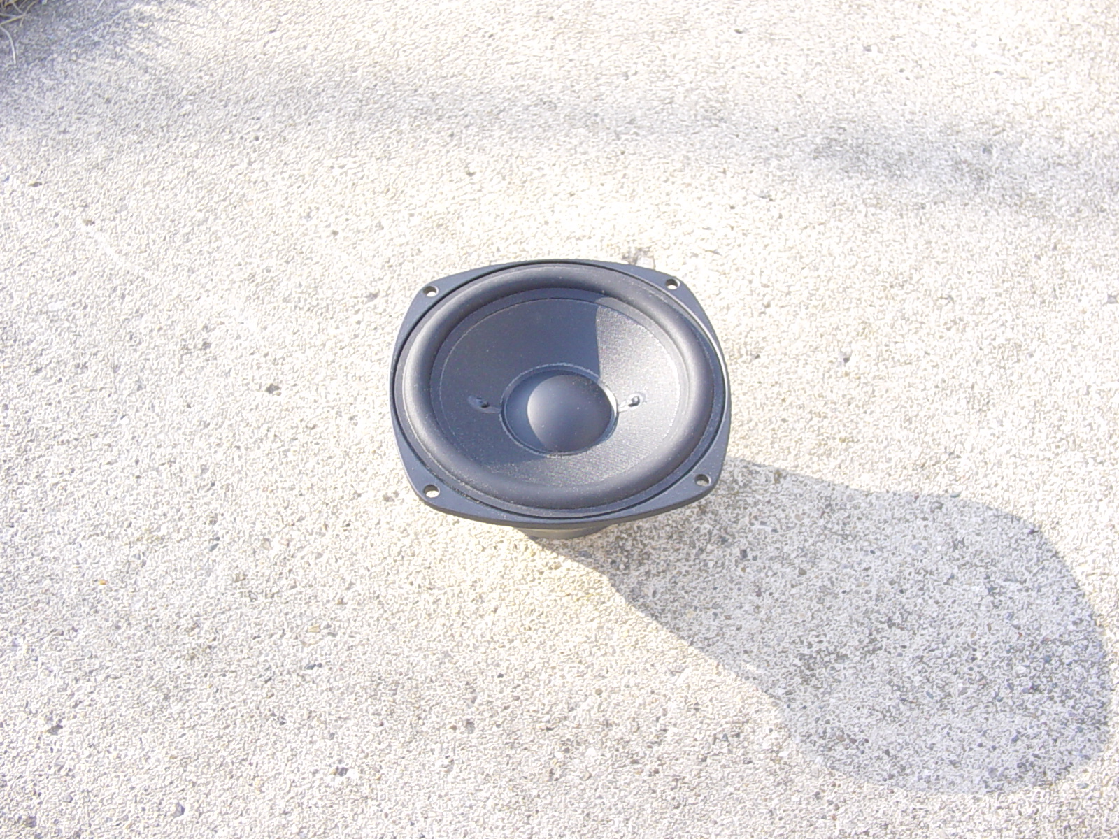
Definitive Technology 5-1/4" Cast-Aluminum Frame Woofer

 (Click to Enlarge)
(Parts Express #299-706) I really like this woofer. It has been described by others as having great resolution and speed, and I feel that it lives up to its reputation. This driver is actually the 5.25" driver used in the soon-to-be-released Definitive Technology Mythos One. Within the Definitive line, this driver is often used with passive radiators. In the StudioMonitor 350, a driver similar to this is paired with an 8" passive radiator (they call it a "pressure-driven subwoofer"), and in the Mythos One, two of these woofers are in an MTM arrangement with an aluminum dome tweeter (Definitive's own design, which is not as robust as the H537) and four 5.25" passive radiators. This driver features a textured homopolymer cone, a cast magnesium basket for high stiffness and low resonance, a butyl rubber surround for improved damping and deeper bass, a soft butyl rubber dustcap, a flat spider, and a 4-layer voice coil on an aluminum former. I myself have been surprised by the bass capability of these little guys. They allow me to extend the response of the enclosure down to about 51 Hz.
Driver Specifications
Manufacturer: Definitive Technology
Model/Manufacturer Part Number: 1144A100 – 172ES
Diameter: 5¼”
Cutout diameter: 4¾”
Surround: Butyl Rubber
Cone Material: Textured Homo-Polymer
Dust Cap Material: Butyl Rubber
Frame Style: Pin-cushion
Basket Material: Magnesium, Cast
Spider: Linear, Not Vented
Vented Pole Piece: no
Magnet Type: Ceramic
Nominal Impedance: 4 Ohms
Power Handling: 75 watts RMS, 100 watts max.
Enclosure
The Numbers
Construction: 3/4” Un-braced MDF, butt joints, glued
Internal Dimensions: 24”x9”x7”
Internal Volume: 1,512 cu. in.
External Dimensions: 25.5”x10.5”x8.5”
Alignment: B4 Bass-Reflex
Porting: Twin 1.5" ports,
Damping Material: Convoluted Open-Cell Foam lining every side of the
enclosure
Finish: Vinyl Laminate – Teak
Grille: Fabric*
Grille Frame Dimensions: 25.5”x8.5”x3/4"*
Grille depth (distance between grille fabric and baffle): 3/4”*
*Grille not yet completed
The Design Phase
I used LinearTeam's WinISD box-modeling software to simulate the enclosure. I designed a bass-reflex enclosure for deep bass, and used two woofers per speaker in an MTM arrangement with the tweeter. This design places one woofer above the tweeter and one below the tweeter to affect the vertical dispersion of the tweeter, preventing harmful ceiling reflections. The original plan was to use a 3" flared port for the bass, but when I saw the size of the ports with the flares, I decided it was overkill, and that the best use for the 3" flared ports would be in a subwoofer enclosure. But that's another project. For the final enclosure, I decided to use a pair of 2.5-inch-long 1.5" ports and tune the enclosure to about 54.5 Hz. This yielded an F3 of about 49.45 Hz.
The Construction Procedure
I assembled the enclosure with my grandfather's help to cut the MDF. I used thick 3/4" MDF to eliminate the need for bracing along the enclosure's short dimensions, and as of yet I have not noticed any problems with enclosure resonances. First, each of the panels were cut. Then, the sides and rear were glued together with Elmer's Glue. I assembled the crossover network and L-Pads with my grandfather's help to solder the parts. The crossover was assembled on a small (8.5"x4") board which was then hot-melt-glued to the rear of the enclosure, just behind the tweeter. The tweeter's L-Pad was glued on separately, to the side of the enclosure opposite the tweeter, but on about the same level. Every bit of interior surface area that was not occupied by the crossover network, ports, or drivers was covered with fire-retardant convoluted acoustic foam (eggcrate-style), glued with hot-melt glue. Then the driver holes were cut in the front panel, and any major blank spots on the interior side of each front panel were covered with convoluted acoustic foam. The port tubes were attached to the rear of the board with hot-melt glue, and I sanded out the front holes to make sure they lined up with the port's edges. Then I glued the front panels to the cabinet, and sanded every face of the cabinet that had edges that weren't quite perfectly matched up during the glue process. Following that, I applied a coat of primer to the front, bottom, and rear of the enclosure. Then my grandfather sprayed the primed surfaces with two coats of black gloss-finish spray paint. The top and sides of the enclosure were covered with Parts Express Vinyl Laminate. (I had a chuckle reading the brand name on the paper backing of the vinyl: "Shanghai Joyous Decorative Materials Co., Ltd.", "Joyous" for short.) Then, I wired the drivers and mounted them up. I discovered that the terminal notch for one of the tweeters had been made too large, and so I had to fill a small hole with speaker-sealing caulk. It has not caused a problem yet. I am simply warning you not to make the same mistake. The tweeter cutout size Parts Express gives for the tweeter is not accurate. I strongly recommend you measure your own tweeter, to avoid mess-ups. I also spaced my drivers too closely together. Please space your drivers about an inch apart for the best results. The tweeter is offset by about 3/4" to lessen diffraction anomalies. You should make sure that no two distances between your tweeter and any baffle edge are the same. Do not mount the tweeter directly in the center of the front panel, either, or frequency response anomalies may result. I have never used a router, and to save time and added complexity, I did not flush-mount the tweeter or the woofers (due largely to the pincushion-shape frame that the drivers use, which is difficult to cut out using a router.) I recommend that if you have the skill, flush-mount the drivers for the best results.
Crossover Network and Internal Wiring
The Numbers
Crossover Network Design
Network Type: Parallel 2nd-order Linkwitz-Riley
network
Impedance Compensaton: No impedance compensation (No Zobel)
Baffle Step Compensation: No Baffle Step Compensation
L-Padding: 5dB Level-Pad network on tweeter
Driver Wiring and Impedance
Woofers: 2x4 Ohms, series wired = 8 Ohms
Tweeter: 1x6 Ohms, wired out-of-phase with the woofers (to compensate for
2nd-order network's 180-degree tweeter phase shift)
Nominal Impedance: 7 Ohms
RMS power handling: 75 watts RMS, 100 watts max.
Internal Wire Size: no less than 18-gague for full current throughput
Crossover Components
Capacitor type(s): Dayton non-polar Metallized
Polypropylene throughout
Inductor type(s): 18-gauge “Perfect Layer” varnished air-core throughout
Resistor type(s): Mills non-inductive wire-wound throughout
Crossover Values
Frequency: 2820 Hz
High Pass Capacitor (C1): 4.7uF (+/- 5%)
High Pass Inductor (L1): 0.7mH (+/- 5%)
Low Pass Capacitor (C2): 3.3uF (+/- 5%)
Low Pass Inductor (L2): 0.9mH (+/- 5%)
L-Pad Resistor in series (R1): 2.5 Ohms (+/- 5%)
L-Pad Resistor in parallel (R2): 8 Ohms (+/- 5%)
The Design Phase
To design the crossover network, I used the online crossover calculators at http://ccs.exl.info/calc_cr.html to get the proper values, since I have no budget for crossover-design software. This crossover is very un-refined. You may decide to carry out more refinements to the design, and perhaps add both BSC (baffle-step compensation) and a Zobel network. I decided that I would not care too much if the crossover wasn't just perfect. I decided to save the extra money on the expensive premium crossover components. I did much canvassing of the forums for information about how to implement a second-order design, and one of the most important parts of the second-order network, I learned, is to make sure that you always wire the tweeter out of phase with the woofers. That means that you should connect what would ordinarily be the positive lead to the negative terminal on the tweeter, and connect the negative lead to the positive terminal on the tweeter. Also, when wiring the woofers, wire them in series to achieve an 8-ohm load. The way to do this is to connect the positive lead to the positive terminal on one of the woofers. Then connect a short lead from the negative terminal on that first woofer to the positive terminal on the second woofer. Finally, connect the negative lead to the negative terminal on the second woofer. This results in an 8-ohm load seen by the amplifier, which is a safe load. If you wire the woofers in parallel, you will create a 2-ohm load on the amplifier, which is unsafe. You will burn up your amplifier.
The Assembly Process
First, plan out the connections. Draw a wiring diagram of the entire speaker. Once you have the network circuits planned, configure the parts on the board that your crossover will be built on such that the parts will be in the vicinity of the other parts involved in that particular function of the network (high pass, low pass, L-pad, etc.) Once you have configured the parts, mark where each part will go. Then, take all the parts off of the board and drill holes for cable ties. I used hot-melt glue for my crossover network, but cable ties will work better. Some of the Mills wire-wound resistors on the L-pad tended to just fall off the board when I used hot-melt glue on them. Attach each part to the crossover board using cable ties. Then, locate each connection to be made and twist each connection together. It has been said that a good solder connection is simply a good connection with solder on it. Double-check your connections against wiring diagrams on the crossover calculator web site. Then solder using rosin-core solder. Start by touching the tip of the soldering iron or gun to the underside of each connection to heat it up so the solder will stick well. Then, when the connection has heated sufficiently, touch the solder to the heated connection. Once all of the appropriate connections have been made, attach the leads that will go to the woofers and tweeter, taking great care to keep track of polarity. You will need to wire the tweeter out of phase later, and it will help greatly if you are able to know what "in phase" is in the first place so you can wire the tweeter out of phase. Once the main input leads and the woofer and tweeter output leads have been attached, attach the crossover board to the rear or the bottom of the speaker enclosure using hot-melt glue. Don't go to the extra bother of using screws, it simply adds difficulty. Once the front panel of the enclosure has been attached and the speaker cabinet has been sanded and finished to the full extent that it will be, the drivers may be wired up and then mounted. Make sure to wire in phase what must be wired in phase and wire out of phase what must be wired out of phase. Wire in series what must be wired in series. If you keep track of everything and make sure you put electrical tape over all of the connections to prevent arcing and short-circuiting, you will be good to go.
soon to come is a feature about how to add grilles to the Project MTMs. The process is fairly self-explanatory though.
The Result
The Numbers
System Frequency Response: 51-20,000 Hz
System Power Handling: 75 Watts RMS - 100 Watts Max.
The Sound
Since I unfortunately have no testing setup to measure frequency response, I cannot offer you a frequency response plot. I can, however, offer you my opinion of how this stacks up to other speakers I have heard in high-end shops such as Ovation. I have found the sound of these speakers to be very detailed. Acoustic guitar sounds magically real, especially when it is well-recorded. Pianos, too. Bela Fleck and the Flecktones sound tight and defined, with nice deep kick drum and fast transient attack on Victor Wooten's bass. These speakers open up a whole new dimension of realism for me, especially when listening to music that requires quick transient response for detail to come through. Tonal balance is very neutral in comparison to my Pioneer/Frieds which were very warm. It is very similar to the Definitive speakers that I have heard at Ovation. The precision and natural, real sound of these speakers caught me off-guard when I first listened to them, an experience I had when listening to Mackie HRM824 studio monitors and marveling at the clarity and definition. Soundstaging is very broad. Imaging isn't as pinpoint as I have heard, but MTMs aren't known for their imaging. All in all, this is the most worthwhile speaker project I have ever carried out. I recommend this especially to beginning DIY Hi-Fi enthusiasts who are just getting started in the DIY speaker world.
Photos
Nobody seems to take you very seriously or give you very much recognition around here unless you provide photos of your work. I took special care to take many pictures, but some of them were lost, including some very interesting ones that detailed the interior of the enclosure. That was a disappointment.
|
Photo |
Description |
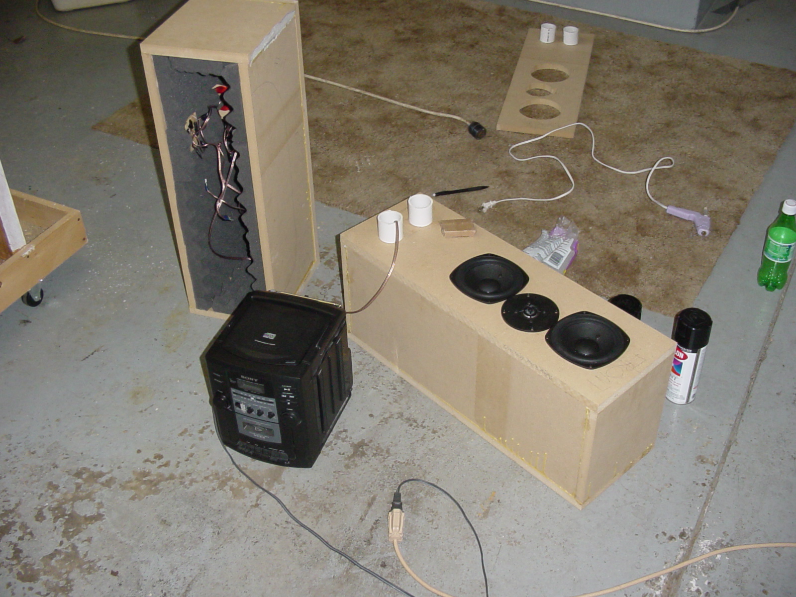 |
That's one speaker hooked up to one channel of a 5-watt-per-channel boom box receiver unit. It's like tasting your cooking. |
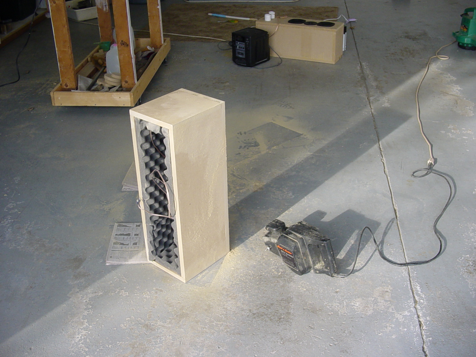 |
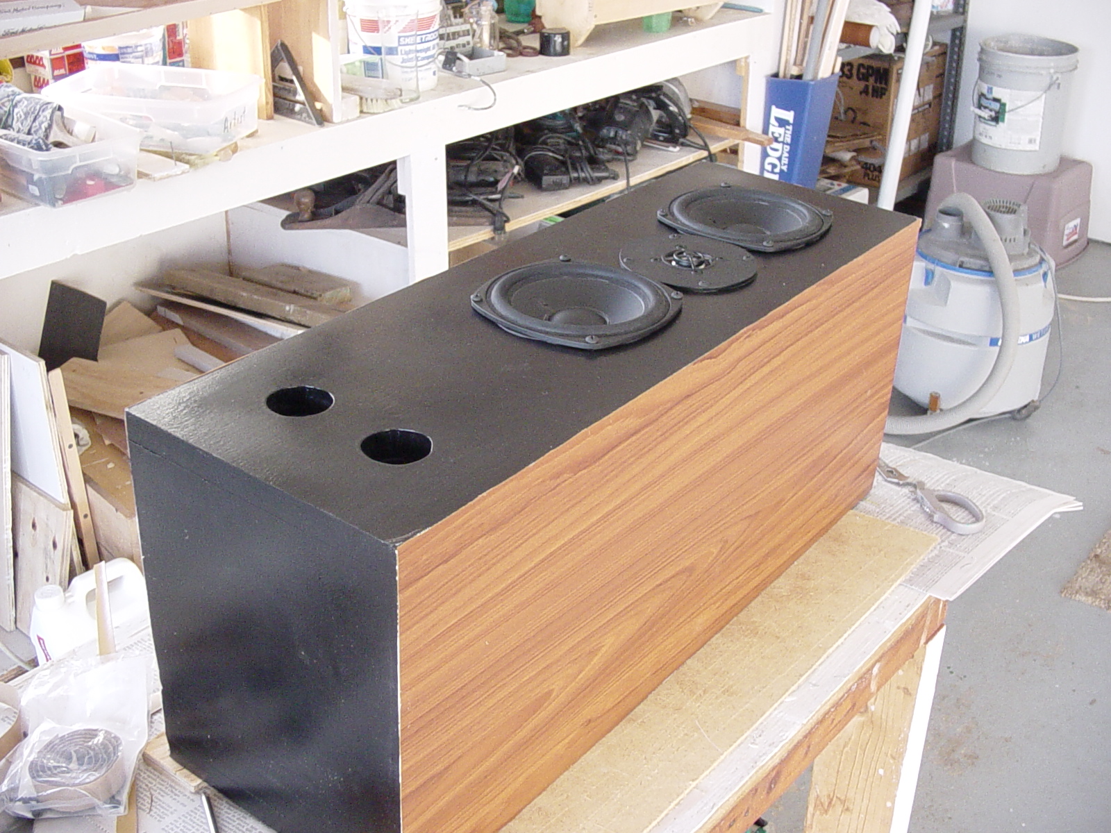
This is a picture during the sanding process. It isn't possible to see as much of the interior of the box as I'd like you to be able to see. |
|
|
This is a picture of the Definitive 5-1/4" midbass that was used. You can really see the detail of the cone. |
|
|
This is a picture of the Seas H537-06 aluminum dome tweeter that was used. Again, I really like the detail. |
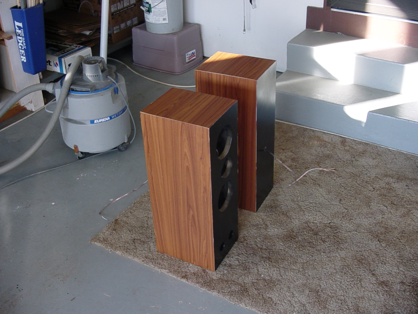 |
This is a picture of the front of one of the finished cabinets and the back of the other. |
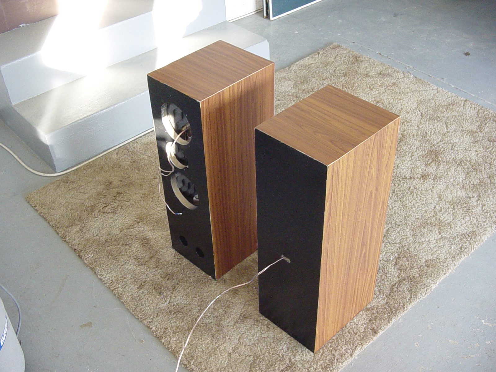 |
This is another picture of the front of the other finished cabinet and the back of the one. I regret that I didn't take a picture like this of the finished speakers. It would have been good to see the back of the speakers as well. |
 |
This is an excellent shot of the drivers and the cabinet together. You can see the gloss of the finish. |
 |
This is an excellent picture of the drivers after they have been mounted. You really get a feel for the quality of the drivers used from this and the previous photo. |
 |
This is a good, bright picture of the front of one of the speaker cabinets. |
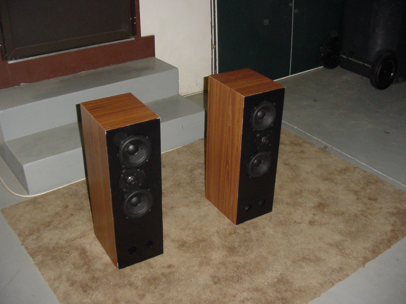 |
Here is a picture of the pair, ready to go home and crank up some tunes. |
Thanks
Here are the organizations and sites I'd like to give thanks to for helping this project to be a success.
http://www.diyaudio.com - The members of the forum on this site were extremely helpful and encouraging to me through all aspects of this project.
http://www.pesupport.com - The members of the forum on this site helped out a bunch by giving me opinions on the drivers and even directing me to another project using these same Definitve Tech 5-1/4" midwoofers. The man who built that project also helped me by giving me some extra pointers.
http://www.partsexpress.com - This site is, without question, the most user-friendly web site that carries speaker parts for sale with the biggest inventory and the most prompt shipping. It is the "first stop" that I recommend for anyone looking for speaker parts and just about every other type of electronics.
My Grandpa - I am only 17 (will be turning 18 in a month, though) and I really appreciated having his help in the construction of these speakers. I could not have done it without him.
Rory Buszka 2003